

Hamamatsu C15550-22UP Single-Photon Camera and PCIe1004 Frame Grabber
Hamamatsu C15550-22UP Single-Photon Camera and PCIe1004 Frame Grabber
The Hamamatsu ORCA-Quest 2 (C15550-22UP) is a high-performance scientific camera based on a qCMOS sensor, featuring 9.4 megapixel (4096*2304 mono16) full-frame resolution and ultra-low readout noise (0.30 e- rms). It is widely used in frontier fields such as light-sheet microscopy, single-molecule fluorescence imaging, super-resolution microscopy, and quantum technology. Especially in quantum computing, this qCMOS camera holds a dominant position.
When using this camera for measurement and control, real-time image acquisition and high-speed, low-latency image processing are often required. Xingce Electronics' PCIe1004 CXP frame grabber has been widely deployed at quantum control customer sites. Paired with Hamamatsu's latest GenICam compatible cameras, it provides customers with plug-and-play, full-function adaptation capabilities.
The PCIe-1004 is a four-channel CoaXPress V2.0 frame grabber with single-channel bandwidth up to 12.5 Gbps (CXP-12) and four-channel aggregated bandwidth of 50 Gbps, capable of fully accommodating the high-speed data stream of C15550-22UP. The onboard Xilinx Kintex UltraScale FPGA and 4 GB DDR4 memory ensure real-time processing of large data volumes. The built-in PoCXP function can directly power the camera via coaxial cable. It also provides Aravis SDK / GenTL SDK and is fully compatible with the camera's GenICam standard interface. Therefore, the PCIe-1004 frame grabber is an ideal platform for comprehensive testing of the camera's ROI, pixel format, trigger mode, digital I/O, LUT, MasterPulse timing control, and other functions.

Hamamatsu ORCA-Quest 2 (C15550-22UP) and PCIe-1004 4 Channel CoaXPress Frame Grabber - Physical Photo
1. PC Hamamatsu ORCA-Quest 2 (C15550-22UP) qCMOS Camera Introduction
The camera tested this time is the GenICam compatible version, the first upgraded version in China. Issues such as water cooling control have been resolved. Compared with the previous old version, the register addresses are significantly different and cannot be used interchangeably.
1. Core Specifications
|
Parameter |
Specification |
|
Sensor Type |
qCMOS image sensor (back-illuminated) |
|
Effective Pixels |
4096 × 2304(940 megapixels) |
|
Pixel Size |
4.6 μm × 4.6 μm |
|
Effective Area |
18.841 mm × 10.598 mm |
|
Peak Quantum Efficiency(QE) |
85%(@460 nm);50%(@300 nm);30%(@900 nm) |
|
Full Well Capacity |
7000 electrons |
|
Readout Noise |
Standard Scan:0.43 e⁻ rms;Ultra-Quiet Scan:0.30 e⁻ rms |
|
Dynamic Range |
23,000:1(rms) |
|
Full Resolution Frame Rate |
Standard Scan 120 fps / Ultra-Quiet Scan25.4 fps(CoaXPress) |
|
Bit Depth |
16 bit/ 12 bit/ 8 bit |
|
Data Interface |
CoaXPress(Quad CXP-6)/ USB 3.1 Gen 1 |
|
Cooling Method |
Forced Air Cooling(-20 ℃)/ Water Cooling(-35 ℃) |
|
Dark Current |
Air Cooling:0.016 e⁻/px/s;Water Cooling:0.006 e⁻/px/s |
|
Lens Interface |
C type interface (also availableF type interface optional) |
2. Four Core Features
- Ultra-low noise performance:ultra-quiet scan mode readout noise only 0.30 e⁻ rms,far below conventionalsCMOS andEM-CCD Camera,aslow-light imaging provide unmatched signal-to-noise ratio。
- Photon number resolution (PNR):with ultra-low readout noise, camera can directly perform precise counting of photoelectrons on each pixel, achieving true quantitative imaging, imaging result meets Poisson statistics.
- Back-Illuminated High Resolution: Using trench-isolated back-illuminated sensor, maintaining high quantum efficiency while effectively suppressing pixel crosstalk,MTF(MTF) performance superior to conventional back-illuminatedsCMOS。
- large amount of pixels and high-speed readout:940 megapixel full-frame resolution withCoaXPress interface can achieve120 fps high-speed readout; throughROI(sub-array) function, frame rate can be further improved.
3. Readout Mode
- Standard Scan(Standard Scan):suitable for conventional high-speed imaging, readout noise 0.43 e⁻ rms。
- Ultra-Quiet Scan(Ultra Quiet Scan):ultra-low noise mode, readout noise 0.30 e⁻ rms,IsPNR prerequisite mode.
- Photon number resolution (PNR)Mode: On ultra-quiet scan basis output photoelectron count values (only through DCAM Configurator Configuration)。
- raw data output (Raw)Mode:output uncorrected raw digital signal for user-defined algorithm processing.
- Light sheet readout mode (Lightsheet Readout):specially designed for light-sheet microscopy design patent function.
4. Software and Interfaces
CameraSupport DCAM-API Driverand GenICam StandardInterface,CompatibleWindows andLinux Operating system。GenICam InterfaceCoverDevice control、Image format、Acquisition control、LUT control, digitalI/O, counter/timer,MasterPulse control, buried data and other function modules.This test usesGenICam Mode。
5. Typical Applications
- Life sciences:light-sheet microscopy, single-molecule fluorescence imaging, super-resolution microscopy, bioluminescence imaging
- Astronomy:lucky imaging, adaptive optics wavefront sensing
- Spectroscopy: Raman spectroscopy, synchrotron radiation X ray imaging
- Quantum Technology: Trapped Ion Quantum Experiments (Benefiting from UV band highQE)
2. PCIe1004 Frame Grabber Introduction
PCIe-1004 4 Channel CoaXPress Frame Grabberis a specially designed for industrial imaging applications high-performance four-channel CoaXPress (CXP) image frame grabber. The board supports latestCoaXPress V2.0 Standard, can through single coaxial cable simultaneously transmit high-speed image data andPower(Power over CoaXPress, PoCXP), simplify system integration and cabling complexity. Additionally, it also provide rich external interface and internal expansion interface, meeting various industrial automation needs.
The PCIe-1004 uses Xilinx Kintex UltraScale FPGA as the core processing unit, providing powerful real-time image preprocessing and flexible user logic expansion. Combined with up to 4GB DDR4 SDRAM onboard memory, it ensures smooth operation even in high frame rate and large data volume scenarios.
Board Functions:
- support four independent CXP 2.0 Input, per channel bandwidth up to12.5Gbps;
- Built-in PoCXP function, supports through coaxial cable camera power supply,Maximum power17WPer channel;
- Provide Aravis SDKandGenTL Producer SDK,compatible mainstream machine vision software platform;
- equipped with rich External I/O interface (such asRS-485, optocoupler isolated input/Output、LVDS、TTL), suitable for complex industrial environments.
Board Diagram

- 26 Pin I/O:panel on26 pin input/Output(I/O)interface, provide external digital signal input/Output。
- LED×4: fourLED indicator.
- HDBNC 12.5Gbps ×4:fourCoaXPress HDBNC Interface,SupportCXP-12 standard, single channel maximum transmit rate12.5 Gbps. Can connect up to fourCoaXPress Camera, achieving high-resolution, high-speed image acquisition. SupportPoCXP Function,asCameraProvide24V Power supply.
- External I/O: externalI/O expansion interface, used to connect additional trigger signals, encoders, user-defined control lines, etc.
- PCIe Gen3 x8 Motherboard Connection Slot: Using PCIe Gen3 x8 physical interface, meeting multi-camera high-speed data return requirements.
- ATX power supply interface 6-pin: PCIe auxiliary power interface, used to connectATX Power,asPoCXP Function provides additional+12V input. When enableCoaXPress Camera'sPoCXP When powered, this power supply must be connected, otherwise the camera cannot be powered.
The camera used in this test is the Hamamatsu C15550-22UP. This camera requires four HDBNC-DIN cables. If only one cable is used, bandwidth will be insufficient and the camera cannot acquire. Camera wiring sequence is shown below.

PCIe-1004 Frame Grabber Side Connection Diagram. The cable numbering between camera and frame grabber must correspond one-to-one.

3. ImgGrab Software Download
Go to the download center of Chongqing Xingce Electronic Technology official website to install ImgGrab. Download URL: https://img-grab.com/jszc

After downloading, follow the prompts to install.

4. Using ImgGrab for Image Acquisition
Open ImgGrab, and the interface shown below will appear.


After selecting the camera, click the button to connect/disconnect (or double-click the camera to connect).

The interface shown below will appear. Click the button to start acquisition.

Acquisition Successful
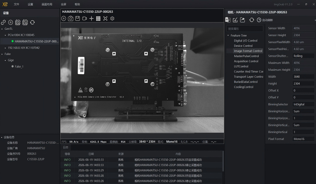
5. Camera Function Testing
1. Camera ROI Function
Default width and height image acquisition

Camera width and height adjusted to half of default values, i.e., Width=2048, Height=1152. Configure and acquire successfully as shown below.

Setting any width and height for image acquisition works normally.
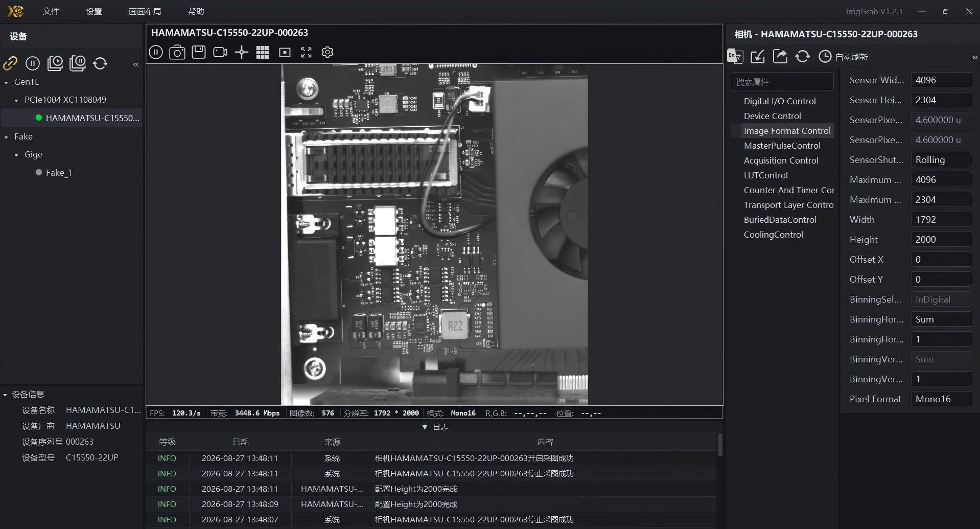
2. Camera PixelFormat Configuration
The camera defaults to Mono16. Now changed to Mono8 and Mono12 for testing.
PixelFormat set to Mono8

PixelFormat set to Mono12

3. Camera Binning Configuration
The camera defaults BinningHorizontal and BinningVertical to 1.
BinningHorizontal and BinningVertical are 1

BinningHorizontal and BinningVertical are 2

When BinningHorizontal and BinningVertical change from 1 to 2, image brightness increases and width/height are halved.
4. Camera Trigger Mode Configuration
CXPTriggerMode
Use CXPTrigger mode. Test directly with CXP cable.
first perform as shown below settings

Then click PCIe1004 frame grabber, click Trigger Control and set as shown below.

Then click Counter And Timer Control and set as shown below.

Click acquire. CXPTrigger mode acquires normally as shown below.

external trigger mode
Camera external trigger test. Trigger source (amplitude 3.3V, bias 1.65V, frequency 70Hz, square wave signal).
Set as shown below. Connect external trigger signal to camera EXT.TRIG interface.

Acquisition result shown below. Frame rate is basically the same as external trigger frequency.

5.LUTControl
Used for mapping and transforming image pixel values, converting input pixel values to output pixel values according to a predefined relationship.
Image acquired with default LUTControl settings

Acquired image with LUTControl enabled and all defaults

Enable LUTControl, adjust LUTOutputMax to half of max 65535. Image becomes significantly darker, all pixel values compressed to half range.

Enable LUTControl, adjust LUTOutputMin to half of max 65535. Image becomes significantly brighter, all pixel values lifted to upper half range.

Enable LUTControl, set LUTInputMin to 10000, LUTInputMax to 40000. Pixels in range 10000~40000 are stretched to 0~65535. Below 10000 become pure black, above 40000 become pure white.

6.DigitalIOControl
DigitalIOControl IsHamamatsuC15550-22UP CameraGenICam feature set one Expert level function category, responsible for managing camera's digital input/output signal line (I/O Line). Corresponding to camera back panel on the4 SMA Interface
DigitalIOControl DefaultSet

UserOutput Fixed Level Output Test
Line0 (External Trigger Input SMA), Line1/2/3 (Timing Output SMA)
1.Line1Test
As shown belowSet

As shown below, Line1 outputs high level

Change TRUE to FALSE, Line1 outputs low level

2.Line2Test
As shown belowSet

As shown below, Line2 outputs high level

Change TRUE to FALSE, Line2 outputs low level

3.Line3Test
As shown belowSet

As shown below, Line3 outputs high level

Change TRUE to FALSE, Line3 outputs low level

7. CounterAndTimerControl (Counter Mode Not Supported)
1.Line1Test
Timer test, output port is camera line1.
As shown belowPerformSet


After setting, click image acquisition. Pulse signals can be observed on oscilloscope.

Click stop acquisition, set TimerDuration to 5000 µs, start acquisition again. Output signal result shown below.
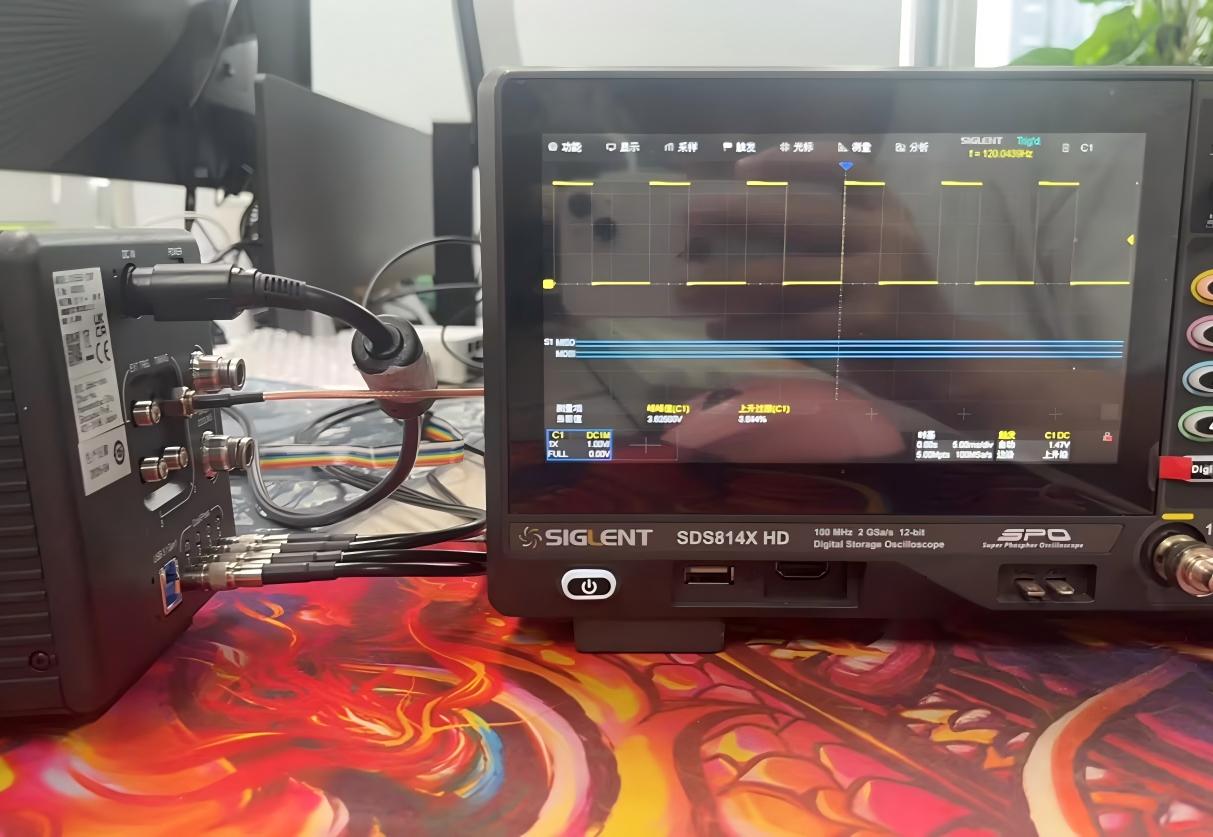
Set TimerTriggerSource to ExposureEnd

Click image acquisition. Pulse signals can be observed on oscilloscope.

2.Line2Test
Timer test, output port is camera line2
As shown belowPerformSet,IfSelectline2AfterDo not haveAs shown belowParameter,PleaseClickRefreshButton


Click image acquisition. Pulse signals can be observed on oscilloscope.

Click stop acquisition, set TimerDuration to 5000 µs, start acquisition again. Output signal result shown below.

Set TimerTriggerSource to FrameEnd and start acquisition again. Output signal result shown below.

3.Line3Test
Timer test, output port is camera line3
As shown belowPerformSet,IfSelectline3AfterDo not haveAs shown belowParameter,PleaseClickRefreshButton


Click image acquisition. Pulse signals can be observed on oscilloscope.

Click stop acquisition, set TimerDuration to 5000 µs, start acquisition again. Output signal result shown below.

Set TimerTriggerSource to ExposureEnd

8.MasterPulseControl
Set parameters as shown below


MasterPulseInterval = Time interval between two adjacent MasterPulse pulses (period), in µs.
|
Item |
Value |
|
Meaning |
Time interval between pulses |
|
Unit |
µs(microseconds) |
|
Range |
5 µs ~ 10 s(i.e. 5 ~ 10000000) |
|
Step |
1 µs |
|
Default Value |
100000 µs(= 100 ms → 10 Hz) |
PulseFrequency = 1 / MasterPulseInterval
|
MasterPulseInterval |
Equivalent frequency |
|
100000 µs(Default) |
10 Hz |
|
10000 µs |
100 Hz |
|
1000 µs |
1 kHz |
|
5 µs |
200 kHz |
|
1 s |
1 Hz |
Image acquisition when MasterPulseInterval=100000 µs shown below

Image acquisition when MasterPulseInterval=10000 µs shown below

Image acquisition when MasterPulseInterval=1000µs shown below

Image acquisition when MasterPulseInterval=5µs shown below

Image acquisition when MasterPulseInterval=1s shown below

According to manual and GenICam implementation, MasterPulse itself cannot be directly routed to Timing SMA port, but a signal synchronized with MasterPulse can be output through Timer mechanism.
The manual states"MasterPulse can be used as programmable timing output reference signal",inGenICam The implementation in is:
1. Using MasterPulse to Drive Camera Acquisition (TriggerSource=MasterPulse0)
2. Timer with FrameEnd as Trigger Source (Triggered at End of Each Frame)
3. Since frame rate is locked by MasterPulse, Timer output is naturally synchronized with MasterPulse
Set as shown below. Use Timing1 (SMA) interface for demonstration.


When MasterPulseInterval=100000 µs, image acquisition is 10 frames/s.

Oscilloscope receives 10Hz pulse signal.

When MasterPulseInterval=10000 µs, image acquisition is 100 frames/s.

Oscilloscope receives 100Hz pulse signal.

MasterPulseInterval can modify MasterPulse period. MasterPulse operates in Timer mode and outputs via
Output via Timing1 (SMA).
9.BuriedDataControl
Open settings and set image format to raw.

As shown below, enable BuriedDataMode and start image acquisition.

Double-click quickly to save and acquire raw format images. The save path is displayed in settings.

Open the just-saved raw file.

Open with hex editor. The first four pixels are 00, 00, FF, FF. Result meets expectations, function is normal.

10. Air-Cooled and Water-Cooled Mode Switching
Switching between air-cooled and water-cooled modes requires DCAM
Open DCAM Configurator

Open Hardware

Switch Cooler Type to Water mode

As shown below, after switching, restart camera to take effect. To switch back, repeat above operations.

After enabling water cooling mode, set CoolerMode Mode1 and Mode2 in ImgGrab


