PCIe-4005 Camera Link Camera Simulator
●Core Platform: FPGA simulation core, PCIe Gen2 x4 industrial board
●Channel Specs: Support Camera Link Base/Medium/Full, max 680MB/s; custom resolution, multi-pixel formats, 6 trigger modes
●Interfaces: Dual SDR Camera Link ports, 26-pin opto-isolated multi-I/O with external trigger
●Performance: 7×24h low-latency stable operation; gradient/BMP/RAW image source, GUI & full SDK
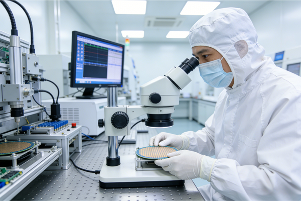
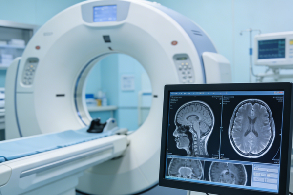
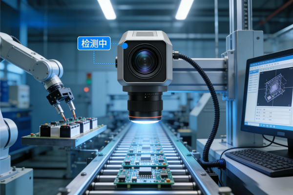
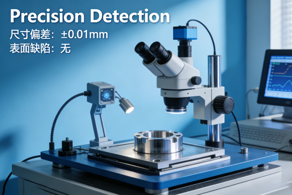
●Applications: Industrial AOI, semiconductor, medical, aerospace vision, frame grabber R&D
●Channel Specs: Support Camera Link Base/Medium/Full, max 680MB/s; custom resolution, multi-pixel formats, 6 trigger modes
●Interfaces: Dual SDR Camera Link ports, 26-pin opto-isolated multi-I/O with external trigger
●Performance: 7×24h low-latency stable operation; gradient/BMP/RAW image source, GUI & full SDK
●Applications: Industrial AOI, semiconductor, medical, aerospace vision, frame grabber R&D
PCIe-4005 Camera Link Camera Simulator
Arbitrary Image Simulation for Camera Link Vision Systems | Flexible Development & Testing Tool

4 Core Advantages
Full Protocol Compatibility & Multi-Mode Adaptation
Compliant with Camera Link standard, fully supports Base/Medium/Full modes, compatible with key control signals like FVAL/LVAL, matching mainstream Camera Link grabbers.
Highly Flexible Configuration & Multi-Scene Coverage
Supports custom image resolution (up to 50000×50000), multiple pixel formats, 6 trigger modes & 3 transmission modes, adapting to diverse simulation scenarios.
High-Performance Hardware & Stable Transmission
Dual high-speed SDR interfaces, throughput up to 680MB/s (Full mode), industrial-grade hardware design ensuring 24/7 stable operation with low latency.
Visual Operation & Easy Secondary Development
Intuitive GUI for parameter configuration, complete SDK support, compatible with Qt5/6 development environment, enabling custom interface and function expansion.
Product Overview
- PCIe-4005 is a dedicated tool for simulating the behavior of real Camera Link cameras. It enables development, testing and verification of image acquisition and data processing functions in vision systems without physical cameras.
- Strictly compliant with Camera Link communication protocol, fully compatible with Base/Medium/Full configuration modes, and supports key data transmission control signals including FVAL and LVAL.
- Equipped with dual high-speed SDR interfaces and PCIe Gen2 x4 host interface, ensuring high-speed data transmission and plug-and-play integration with industrial computers/server chassis.
- Offers multiple image source inputs (built-in patterns/local images/bin files) and flexible parameter configuration, supporting various trigger modes to meet simulation needs of different application scenarios.
- Comprehensive I/O interfaces: 26-pin D-SUB External I/O, 26-pin INTERNAL I/O header, including differential I/O, optically isolated I/O, LVDS/TTL interfaces and 24-way GPIO, supporting inter-board communication and external device linkage.
- Provides complete SDK development package with API for full parameter configuration, open hardware resources and detailed development documentation, facilitating secondary development and customized solutions.
Key Features
- Dual high-speed SDR interfaces, compliant with Camera Link standard, supporting Base/Medium/Full transmission modes (throughput: 255MB/s/510MB/s/680MB/s).
- PCIe Gen2 x4 host interface, plug-and-play, compatible with most industrial computers and server chassis.
- Flexible image simulation: Supports default gradient patterns, custom gradient patterns and local images (BMP/JPEG/PNG/TIFF/bin/raw formats), max resolution up to 50000×50000.
- Rich pixel format support: Mono8/10/12/14/16, RGB8/10/12, adapting to different vision system requirements.
- 6 trigger modes: Software Trigger, Rising Edge Trigger, Falling Edge Trigger, High Level Trigger, Low Level Trigger, Immediate Trigger (custom internal frequency).
- 3 transmission modes: Finite Frame Mode, Continuous Transmission Mode, Continuous Loop Mode, suitable for different data volume simulation scenarios.
- Multi-channel topology support: 1X1/1X2/1X3/1X4/1X8_1Y configurations, enabling 1-8 pixels per pixel clock transmission.
- Comprehensive I/O configuration: 26-pin D-SUB External I/O, dual SDR Camera Link interfaces, 26-pin INTERNAL I/O header (24-way GPIO direct to FPGA).
- Visual operation software: Supports automatic parameter application for images, configuration save/load, real-time transmission control and status monitoring.
- Secondary development support: Compatible with Qt5/6 development environment, complete SDK with API for full function control and custom interface development.
- Industrial-grade reliability: Air cooling design, ESD/overvoltage protection for I/O interfaces, stable operation under harsh industrial environments.
Technical Parameters
| Item | Specification |
|---|---|
| Interface Standard | Camera Link (Base/Medium/Full), dual high-speed SDR interfaces |
| Host Interface | PCIe Gen2 x4, plug-and-play, no external power required |
| Transmission Mode | Base (255MB/s), Medium (510MB/s), Full (680MB/s, 1X8_1Y 8bit only) |
| Image Simulation | Built-in gradient patterns, custom gradient patterns, local images (BMP/JPEG/PNG/TIFF/bin/raw) |
| Max Resolution | 50000×50000 (custom gradient patterns) |
| Pixel Formats | Mono8/10/12/14/16, RGB8/10/12 |
| Trigger Modes | Software Trigger (0x0), Rising Edge (0x1), Falling Edge (0x2), High Level (0x8), Low Level (0x10), Immediate (0x20) |
| Transmission Modes | Finite Frame, Continuous Transmission, Continuous Loop |
| Topology Configurations | 1X1/1X2/1X3/1X4/1X8_1Y |
| I/O Interfaces | 26-pin D-SUB (External I/O), dual SDR Camera Link, 26-pin header (24-way GPIO, LVDS/TTL, optically isolated I/O) |
| Software Compatibility | Windows 10/11, Qt5/6 development environment, custom SDK |
| Mechanical Dimensions | Standard PCIe card, 168mm(L)×111mm(W) (compatible with PCIe Gen2 x4 slots) |
| Operating Environment | Dry, dust-free, low-vibration, anti-electromagnetic interference; air-cooled heat dissipation |
Product Interface Diagram
Product Dimension Drawing
Safety Warnings (Mandatory)
- Do NOT install/uninstall the card with power on: Turn off the host and disconnect the power cord first; wear an anti-static wristband to avoid electrostatic damage to chips.
- Proper I/O interface usage: Connect 100Ω terminating resistor for LVDS input of External I/O; ensure external trigger signals match the card's voltage level to prevent overvoltage damage.
- Coordinate parameter configuration: Match transmission mode with channel topology; ensure consistent resolution for local images; manually set resolution accurately for bin/raw formats.
- Software installation requirements: Install drivers and dedicated library files before running the host software; check hardware connection and driver version if the device is not recognized.
- Adequate heat dissipation: Ensure good chassis ventilation during operation to avoid device throttling or crash due to high temperature; reset or reinstall the card if abnormal during long-term use.
- Memory requirement for large-resolution transmission: Ensure sufficient host memory for custom high-resolution gradient images; use Continuous Transmission/Loop mode for large data volume simulation.
Quick Start Guide
- Hardware Installation: Ensure the host supports PCIe Gen2 x4 slots; power off the host, insert the card into the idle PCIe slot, fasten the bracket screw; connect external I/O devices (trigger source/grabber) to D-SUB26/SDR interface, then power on the host and install drivers.
- Software Installation: Install dedicated library files and host software (supports Windows 10/11); for secondary development, install Qt5/6 environment and import the SDK package.
- Parameter Configuration:
- File Settings: Select data source (local image/bin file), browse to set file path; local images support "one-click auto-apply" resolution, while bin files require manual resolution and padding settings.
- Parameter Settings: Choose data source (local image/hardware test pattern), configure device topology, pixel format, padding mode; select trigger/transmission mode; set timing parameters, resolution, frame rate and running time (0 for infinite run).
- Start & Run: Click "Start Transmission" after configuration; use "Software Trigger" for single-frame data in software trigger mode; stop transmission with "Stop" button or restore default parameters with "Reset".
- Save/Load Configuration: Click "Save Configuration" to generate a configuration file for quick parameter restoration later without reconfiguration.
- Secondary Development: Call API functions (e.g., PCIe4005Start/Stop) to control the device; configure core parameters via API for automated simulation; customize GUI and expand functions based on Qt5/6.
Typical Application Scenarios
半导体检测 医疗成像 航空航天 工业自动化 机器视觉 精密检测