

CoaXPress Testing Based on MicroChip VIDEO-DC-CXP Board
CoaXPress Testing Based on MicroChip VIDEO-DC-CXP Board
1 Introduction
1.1 Introduction to CoaXPress
CoaXPress (CXP for short) is a camera data transmission standard using coaxial cables for interconnection. It is mainly used to replace the previous Camera Link protocol, and is commonly used in scientific cameras, industrial cameras, medical imaging, aerospace and defense scenarios. Due to cable form and transmission speed limitations, Camera Link is no longer suitable for the growing demand for data bandwidth.
CXP is an asymmetric high-speed point-to-point serial transmission protocol, mainly used for transmitting video and still images, mostly via single or multiple coaxial cables. The latest 2.0 standard supports a maximum speed of 12.5Gbps per lane. In addition to image data, each lane can transmit low-speed control signals (41.6Mbps) and supply power to cameras via the cable, known as "Power-over-Coax". A single cable can reach up to 100 meters in length.
- Up to 12.5Gbps line rate per coaxial cable; single or multiple cables can be used, e.g., 4 cables provide up to 50Gbps data rate
- Long cable length: 100m at 3.125 Gbps, 35m at 12.5Gbps
- Real-time, low-latency data transmission with fixed latency
- Precise real-time triggering, supporting trigger transmission via coaxial cables without extra communication cables
- Flexible and reliable performance using standard coaxial cables (RG59, RG6; RG6 recommended)
- Easy integration: image data, control communication, and power share one cable, with low-cost cables
CXP is a point-to-point scalable interface. The physical medium between the device and the HOST is a 75Ω coaxial cable. Each CXP interface includes 1 MASTER connection and several optional SLAVE connections, each requiring one coaxial cable. Connections are numbered: MASTER is fixed as 0, and SLAVE interfaces are numbered sequentially.
 Figure 1-1 CXP Connection Structure
Each connection includes the following functions:
- High-speed serial data (typically Device to Host Downconnection), up to 12.5 Gbps.
- Low-speed serial data (typically Host to Device Upconnection), up to 41.6 Mbps.
- Power supply (Host to Device), up to 13W.
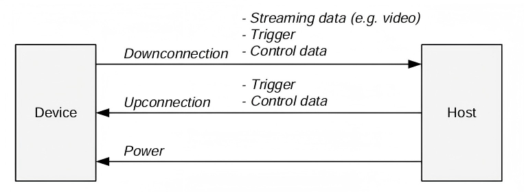 Figure 1-2 DownConnection and Upconnection
Table 1-1 CoaXPress Supported High-Speed Signal Rates
| CXP Speed | Bit Rate (Gbps) |
|---|---|
| CXP-1 | 1.250 |
| CXP-2 | 2.500 |
| CXP-3 | 3.125 |
| CXP-5 | 5.000 |
| CXP-6 | 6.250 |
| CXP-10 | 10.000 |
| CXP-12 | 12.500 |
2 Product Overview
Xingce Electronics provides CoaXPress series products compatible with any FPGA platform. We have fully or partially verified platforms including Xilinx, Microchip, Fudan Microelectronics, and Elinksys. We are committed to providing customers with world-leading vision solutions.
2.1 PCIe-1004 4 Channel CoaXPress Frame Grabber
The PCIe-1004 4 Channel CoaXPress Frame Grabber from Chongqing Xingce Electronics is a high-performance 4-channel CoaXPress (CXP) frame grabber designed for industrial imaging applications. The board supports the latest CoaXPress V2.0 standard, enabling simultaneous transmission of high-speed image data and power (Power over CoaXPress, PoCXP) over a single coaxial cable, simplifying system integration and wiring complexity. It also provides rich external and internal expansion interfaces to meet various industrial automation needs.
The PCIe-1004 uses Xilinx Kintex UltraScale FPGA as the core processing unit, delivering powerful real-time image preprocessing capabilities and flexible user logic expansion options. With up to 4GB DDR4 SDRAM on-board memory, it ensures smooth operation even in high-frame-rate, large-data-volume scenarios.
Board Features:
- Supports 4 independent CXP 2.0 inputs, up to 12.5Gbps bandwidth per channel;
- Built-in PoCXP function, supports power supply to cameras via coaxial cables, max 17W per channel;
- Provides Aravis SDK and GenTL Producer SDK, compatible with mainstream machine vision software platforms;
- Equipped with rich External I/O interfaces (RS-485, opto-isolated I/O, LVDS, TTL) for complex industrial environments.
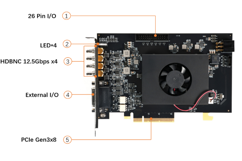 Figure 1-1 PCIe-1004 Interface Diagram
- 1. 26 Pin I/O: 26-pin digital input/output interface on the panel for external digital signal I/O.
- 2. LED×4: Four LED indicators.
- 3. HDBNC 12.5Gbps ×4: Four CoaXPress HDBNC interfaces supporting CXP-12 standard, up to 12.5 Gbps transmission rate per channel. Connect up to four CXP cameras for high-resolution, high-speed image acquisition. Supports PoCXP for 24V camera power supply.
- 4. External I/O: External I/O expansion interface for connecting extra trigger signals, encoders, user-defined control lines, etc.
- 5. PCIe Gen3 x8 Motherboard Slot: PCIe Gen3 x8 physical interface for high-speed data backhaul of multi-camera systems.
- 6. ATX power supply interface 6-pin: PCIe auxiliary power interface for ATX power input, providing extra +12V for PoCXP. Must be connected when PoCXP is enabled for cameras, otherwise power supply fails.
2.2 VIDEO-DC-CXP (CoaXPress FMC)
The CoaXPress board supports 12.5G CoaXPress PHY and includes out-of-the-box reference designs for rapid prototyping. Microchip's CoaXPress FMC daughter card is a hardware evaluation platform for testing the CoaXPress protocol. Designed for easy prototyping of mainstream imaging and video protocols, it supports MIPI CSI-2 TX, MIPI CSI-2 RX, HDMI 1.4 TX, HDMI 2.0, DSI, and HD/3G/6G/12G SDI. The kit features a PolarFire FPGA with 300k logic elements (LE), integrated DDR4 and SPI-flash, ideal for medium-bandwidth imaging and video applications.
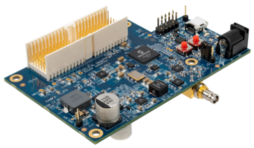 Figure 2-2 VIDEO-DC-CXP
Board Specifications:
- 12.5G CoaXPress PHY
- PolarFire device with 100k LE in FCSG325 package
- Amphenol FCI connector
- 1 Micro BNC connector – TX (Transmit)
- JTAG – Programming Interface (FP4)
3 Operating Instructions
Software Preparation:
- Xingce Electronics —— ImgGrab
- MicroChip —— FlashPro Express
Download the matching .job file for the board from the MicroChip official website. Connect the VIDEO-DC-CXP to the host via JTAG, connect VIDEO-DC-CXP to PCIe-1004 with a CXP cable, and power the VIDEO-DC-CXP board. The FMC daughter card can be powered by an external power adapter or CXP cable, with the J7 jumper cap selecting the power mode. The figure below shows power supply via an external power adapter.
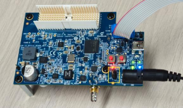 Figure 3-1 Hardware Connection
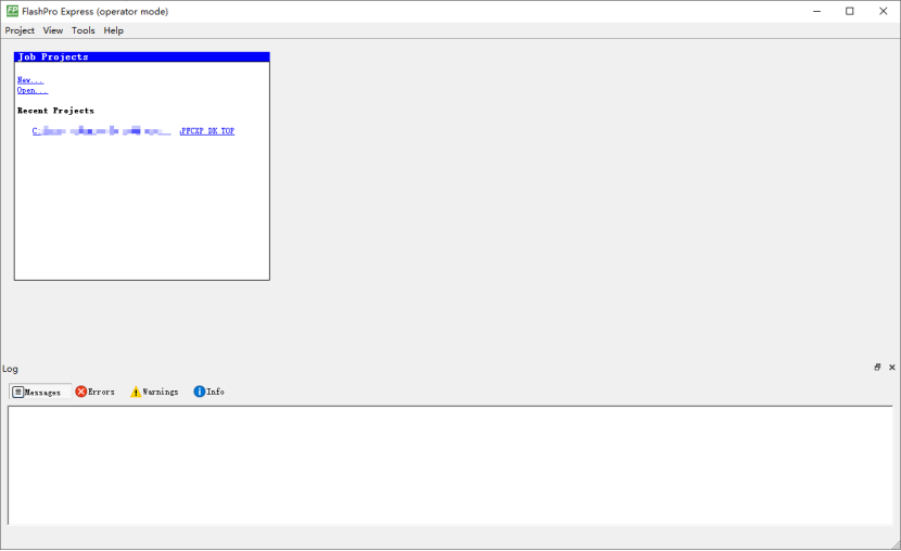 Figure 3-2 FlashPro Express Software Interface
Click "New", select the downloaded job file in the pop-up dialog, choose a folder for the project, and click OK to complete configuration.
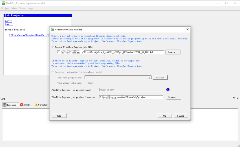 Figure 3-3 Create New Job Project
After clicking OK, a new dialog will pop up. Click RUN in the dialog to start programming.
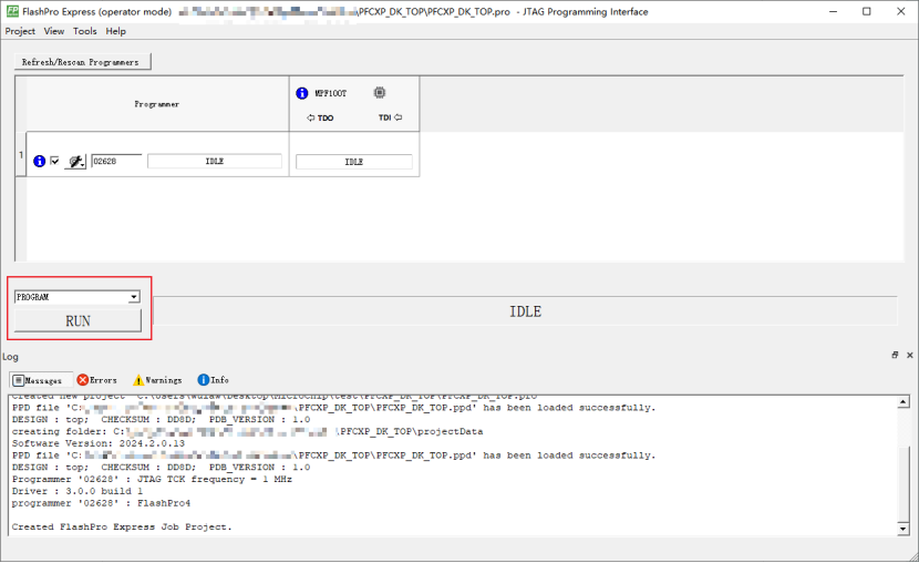 Figure 3-4 Start Programming
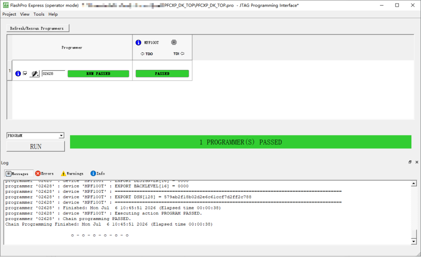 Figure 3-5 Programming Successful
Open ImgGrab, the software will refresh devices automatically.
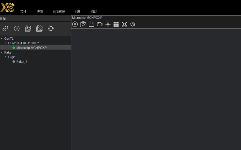 Figure 3-6 ImgGrab Interface
The PCIe-1004 successfully identifies the VIDEO-DC-CXP board and completes control and acquisition. No image data is displayed as no camera is connected.

