How CoaXPress Achieves Bidirectional Data Transmission and Power Supply Over a Single Cable
How CoaXPress Achieves Bidirectional Data Transmission and Power Supply Over a Single Cable
This is a clever engineering design. CoaXPress supports full-duplex bidirectional data transfer plus power delivery using just one coaxial cable. Its implementation provides valuable reference for other serial interfaces, especially applications with strict limits on cable quantity and length. A single coaxial cable handles everything perfectly!
Overall Architecture
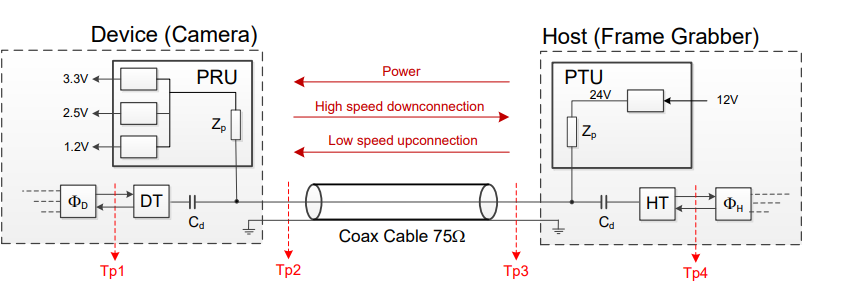
Definitions of terms in the diagram:
- Device: Industrial Camera
- HOST: Frame Grabber / Image Acquisition Device
- PRU (Power Receive Unit): Only required for Power-over-Cable function
- PTU (Power Transfer Unit): Only required for Power-over-Cable. It boosts 12V input up to 24V and injects DC power into the coaxial cable.
Why 24V instead of 12V? To deliver up to 13W power, 12V would result in excessive current and large cable loss. Higher voltages would drastically raise hardware cost, so 24V is the balanced optimal solution. - ΦD: Integrated high-speed serial transmitter + low-speed serial receiver
- DT (Device Transceiver): Simultaneously transmits high-speed data to the cable and receives low-speed uplink data
- Cd: AC coupling capacitor on the device side, used to block DC voltage
- Zp: Inductive low-pass filter placed between power supply and data line. Its impedance must be far higher than the 75Ω characteristic impedance of the coax. The recommended value is 11.5 µH (± 30 %)
- HT (HOST Transceiver): Receives high-speed downlink data and transmits low-speed uplink data over the cable
- ΦH: Integrated high-speed serial receiver + low-speed serial transmitter
- Tp1, Tp2, Tp3, Tp4: Electrical test points for signal compliance verification
The signal flow can be understood with the next diagram: High-speed signal = High Speed Downconnection; Low-speed signal = Low Speed Upconnection.
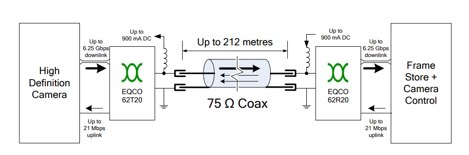
For DT and HT physical implementation: Microchip is currently the only supplier of dedicated transceiver ICs. EQCO62X20 series for CoaXPress 1.1; EQCO125X40 series for CoaXPress 2.1. The block diagram below shows a CoaXPress 1.1 hardware implementation.
High-Speed Signal Electrical Specifications
High Speed Connection Cable Driver
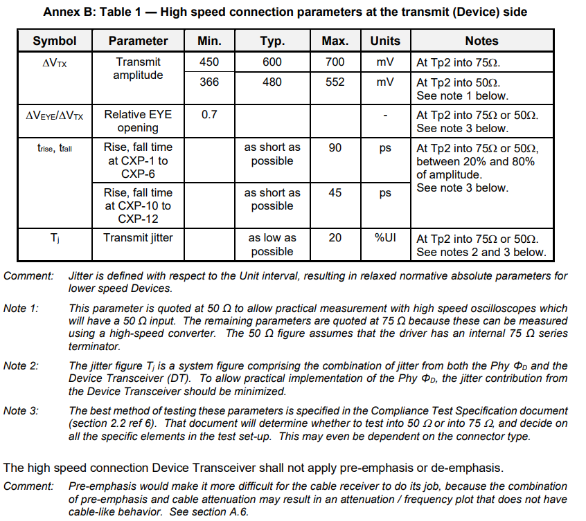
The eye diagram below defines the electrical performance at test point Tp2, including signal amplitude, rise/fall time and jitter under standard test patterns.
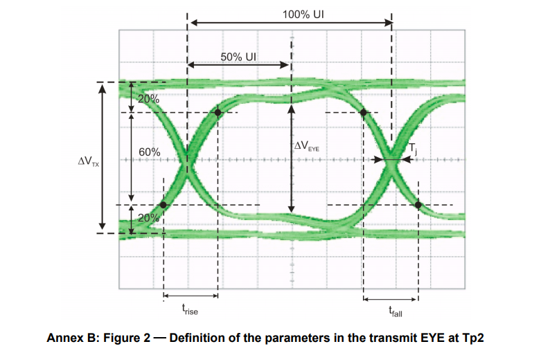
The corresponding electrical parameters are listed in the table. For 75Ω coaxial cable, the typical peak amplitude of high-speed signal is 600mV. The DT converts differential P/N signals into single-ended signal: P feeds the coax cable, N connects to ground.
High Speed Connection Cable Receiver
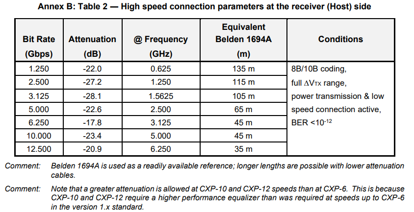
The HT receiver includes an equalizer circuit to compensate for frequency-dependent cable attenuation across different data rates. Equalization parameters shall follow the reference table below.
Low-Speed Signal Electrical Specifications
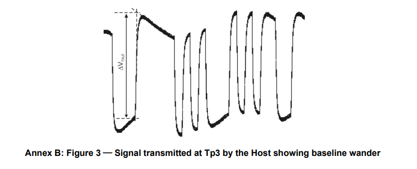
Baseline Wander of Low-Speed Signals
The inductor Zp forms a high-pass filter, which introduces DC offset and baseline drift for low-speed data (20.83Mbps and 41.6Mbps). Increasing inductance can mitigate drift, but considering component size, 11.5 µH (± 30 %) remains the recommended value.
Low Speed Connection Cable Driver
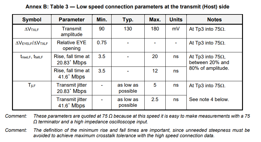
The eye diagram below characterizes low-speed uplink signals measured at Tp3.
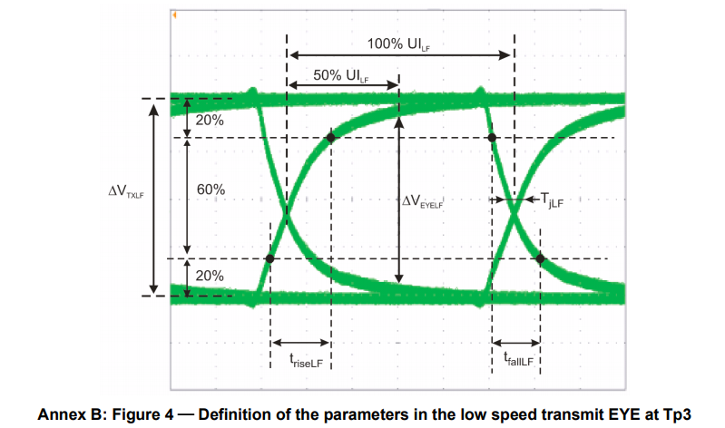
Electrical specs are fixed for amplitude, edge rate and jitter. Typical signal swing is 130mV, different from high-speed 600mV swing. This amplitude difference reduces crosstalk and makes two signal layers easily distinguishable.
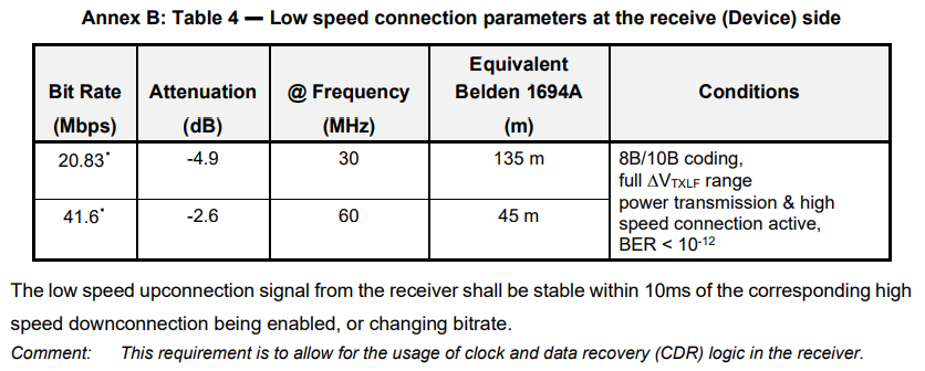
Low Speed Connection Cable Receiver
Key requirement: Low-speed control signals must stay stable for at least 10ms during high-speed link enable or bitrate reconfiguration.