
Commercial Aerospace and CoaXPress (CXP)
Commercial Aerospace and CoaXPress (CXP)
Introduction to CoaXPress
CoaXPress (referred to as CXP) is a camera data transmission standard that uses coaxial cables for interconnection, mainly used to replace the previous Camera Link protocol. It is commonly found in scientific cameras, industrial cameras, medical imaging, aerospace defense and other scenarios. Due to cable form factors, transmission speeds, and other reasons, Camera Link is no longer suitable for the ever-growing demand for data bandwidth.
CoaXPress is an asymmetric high-speed point-to-point serial transmission protocol, primarily used for transmitting video and still images, with cables mostly using single or multiple coaxial cables. The current 2.0 standard has a maximum speed of 12.5Gbps per lane. In addition to transmitting image data, each lane can also transmit low-speed control signals (41.6Mbps) and can supply power to the camera using the same cable, known as "Power-over-Coax", with a maximum single cable length of up to 100 meters.
- Maximum line rate of 12.5Gbps per coaxial cable; multiple cables can be used (e.g., 4 cables can provide up to 50Gbps data rate)
- Long cable lengths: up to 100m at 3.125 Gbps, and up to 35m at 12.5Gbps
- Real-time and low-latency data transmission with fixed latency
- Precise real-time triggering capability, supporting trigger transmission via coaxial cable without additional communication cables
- Flexible and reliable performance using standard coaxial cables (e.g., RG59 and RG6 specifications, RG6 recommended)
- Easy integration: images, control communication, and power can use the same cable at low cost
CoaXPress is a point-to-point scalable interface where the physical medium between devices and HOST is 75Ω coaxial cable. Each CoaXPress interface includes 1 MASTER connection and several optional extended SLAVE connections, with each connection requiring 1 coaxial cable. Devices typically number these connections, with MASTER fixed at 0 and SLAVE extended interfaces incrementing sequentially.
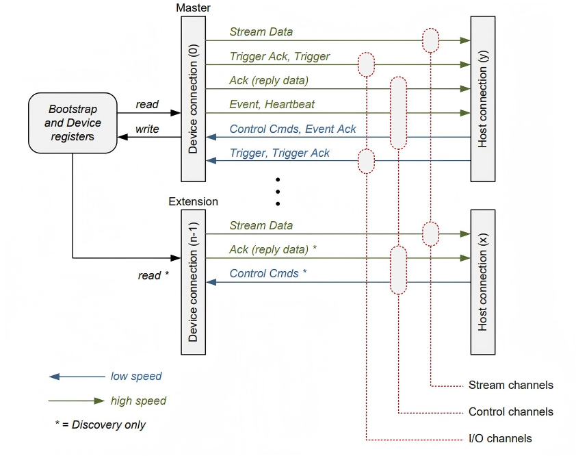 Figure 1 CoaXPress Link Structure
Each connection includes the following functions:
- High-speed serial data (typically Device to Host Downconnection), up to 12.5 Gbps.
- Low-speed serial data (typically Host to Device Upconnection), up to 41.6 Mbps.
- Power supply function (Host to Device), up to 13W.
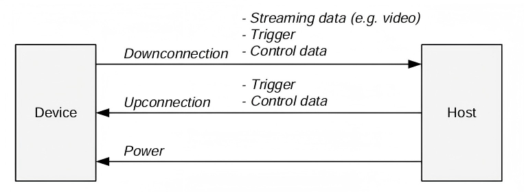 Figure 2 DownConnection and Upconnection
Table -1 High-speed Signal Rates Supported by CoaXPress
| CoaXPress Speed | Bit Rate (Gbps) |
|---|---|
| CoaXPress-1 | 1.250 |
| CoaXPress-2 | 2.500 |
| CoaXPress-3 | 3.125 |
| CoaXPress-5 | 5.000 |
| CoaXPress-6 | 6.250 |
| CoaXPress-10 | 10.000 |
| CoaXPress-12 | 12.500 |
CoaXPress in Commercial Aerospace
Benefiting from CXP's advantages of single-cable high speed, bidirectional communication, power supply capability, and scalability, it is accelerating deployment in commercial aerospace telemetry, image transmission, and on-orbit device collaborative control, and is currently applied in new satellite systems. Star Test Electronics can provide a complete ground test system with full transmit and receive testing capabilities.
Channel CoaxPress HIL System Hardware-in-the-Loop Testing
HIL (Hardware-in-the-Loop) is a real-time simulation testing technology widely used in automotive, aerospace, power electronics, industrial control, rail transit and other fields. It is used for high-fidelity, safe, and repeatable testing of controllers (ECU, FPGA, PLC, etc.) during early development and fault debugging phases.
As a widely accepted and applied image interface technology, CoaXPress has significant application and testing requirements in industrial sites, scientific research experiments, aerospace and other fields. Star Test Electronics provides a flexible CoaXPress V2.0 HIL system to address users' development and testing needs, helping users quickly locate issues and efficiently build test systems.
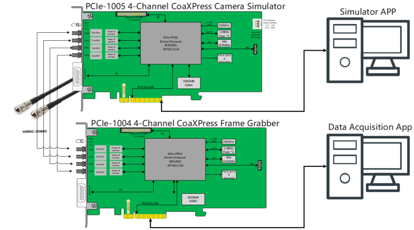 Figure 1-3 PCIe-1004-1005 4 Channel CoaXPress HIL System
The PCIe-1004-1005 4 Channel CoaXPress HIL System mainly consists of the following components:
- PCIe-1005 4-Channel CoaXPress Camera Simulator (simulates CoaXPress cameras)
- PCIe-1004 4-Channel CoaXPress Frame Grabber (acquires CoaXPress camera data)
- HDBNC-HDBNC cables
- GUI software
Regarding HDBNC-HDBNC cables:
 Figure 1-4 Common CoaXPress Interfaces
PCIe-1005 4-Channel CoaXPress Camera Simulator:
- 4-channel CoaXPress HDBNC interfaces with EQCO125x40 equalizers for CoaXPress transmission
- PCIe Gen3x8 high-speed interface with 4GB on-board cache
- Compatible with CoaXPress 1.0/2.0, with maximum bandwidth of 12.5Gbps per channel;
- Supports simulation of arbitrary image formats and sizes;
- Supports line scan and area scan image output;
- Arbitrary configuration of image output timing;
- Supports FPGA-built-in image sources and software-defined arbitrary image sources; images read from folders supporting common formats (png, bmp, jpeg, tiff) as well as raw format images and raw video files
- Supports cyclic image output, trigger output, and continuous output
- Equipped with rich External I/O interfaces (e.g., RS-485, optocoupler isolated input/output, LVDS, TTL) suitable for complex industrial environments and various trigger signal generation scenarios
- Supports custom protocols, suitable for aerospace camera applications
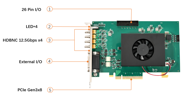 Figure PCIe1005 Interface Diagram
PCIe-1004 4-Channel CoaXPress Frame Grabber:
- 4-channel CoaXPress HDBNC interfaces with EQCO125x40 equalizers for CoaXPress reception
- PCIe Gen3x8 high-speed interface with 4GB on-board cache
- Compatible with CoaXPress 1.0/2.0, with bandwidth up to 12.5Gbps per channel;
- Built-in PoCoaXPress function supporting camera power supply via coaxial cable;
- Provides AravisSDK and GenTLProducer SDK compatible with mainstream machine vision software platforms;
- Equipped with rich External I/O interfaces (e.g., RS-485, optocoupler isolated input/output, LVDS, TTL) suitable for complex industrial environments
- Supports custom protocols, suitable for aerospace camera applications
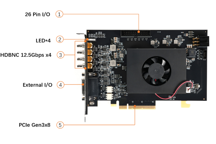 Figure 1-1 PCIe-1004 Interface Diagram
For detailed product information, please refer to the corresponding product manuals.
Application Scenarios
From a protocol perspective, there are two main application scenarios: one simulating standard CoaXPress cameras for industrial and scientific research applications, and the other simulating non-standard CoaXPress cameras for special scenarios such as aerospace.
- Standard CoaXPress Cameras: PCIe-1005 can simulate standard CoaXPress2.0 protocol cameras, suitable for industrial, scientific research and other scenarios using standard CoaXPress cameras.
- Non-standard Aerospace Cameras: Most aerospace cameras use CoaXPress electrical standards but not CoaXPress protocol standards, making them incompatible with standard CoaXPress simulators for HIL testing. The PCIe-1004-1005 HIL System supports HIL testing of non-standard CoaXPress cameras to meet these application requirements.
Application Case 1
System Technical Parameters and Performance Requirements
Camera Parameter Settings
- Supports four-channel independent data generation with customizable line rates and data structures via upper computer configuration; uses 8B/10B encoding with synchronization and alignment on the receiving end based on custom formats of K28.5 characters.
- Multispectral Camera: 1.25Gbps line rate, 125MHz reference clock; data includes auxiliary data (fixed + non-fixed parameters) and image data with custom frame header/trailer (/SF//EF/) and idle state transmission of /SP/ synchronization characters.
- Hyperspectral Visible Light Camera: 3.125Gbps line rate supporting push-broom/area scan modes; each line contains auxiliary data and image regions with auxiliary data inserted in 8 lines; custom frame header/trailer and idle synchronization characters.
- Hyperspectral Infrared Camera: 5Gbps line rate outputting 257 lines/frame (first line auxiliary data, subsequent 256 lines image data) including camera ID, time information, checksum and other fields; custom frame header/trailer and idle synchronization characters.
- Standby Interface: Customizable GT core configuration with no specified data format for now.
- FPGA software GT parameters support user modification; upper computer provides SDK and corresponding GUI code for easy customization.
- Supports frame rate/size modification and trigger settings.
- Auxiliary data uses CSV files for easy editing; image data supports tiff, bmp, raw formats and bin binary data.
Data Display and Storage
- Supports independent reception and storage of four-channel CoaXPress data with different line rates and structures.
- Supports long-duration, large-file continuous playback and storage.
- Data storage must follow "time + channel" naming convention with SSD as storage medium in data receiving host.
- Compatible with various data formats output by simulation sources.
- FPGA software GT parameters support user modification; upper computer provides SDK and corresponding GUI code for easy customization.
- User-stored data in bin format; video playback allows loading auxiliary data formats and removing auxiliary data for frame extraction display;
PCIe1005 Data Simulation Source
Composition
The Camera CoaXPress Data Simulation Source mainly consists of a data simulation host, CoaXPress data simulation source board, and CoaXPress cables. The CoaXPress data simulation source module uses Hello FPGA's PCIe-1005 4-Channel CoaXPress Camera Simulator board, with the main control upper computer software of the data simulation host using supporting software for the simulation source module. Configuration via the upper computer software enables generation of four-channel independent data with different line rates and structures.
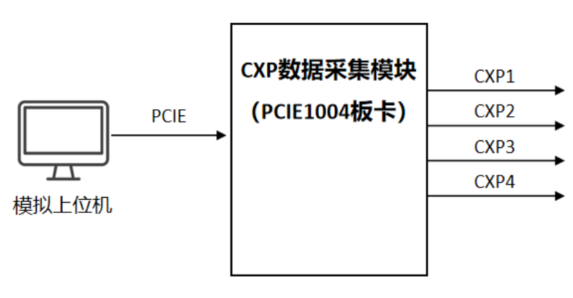 Figure -1 Camera CoaXPress Data Simulation Source Composition Diagram
Software Description
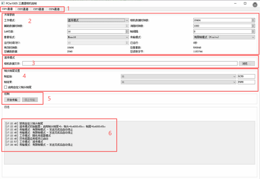
The 1005 QT interface mainly includes six parts:
- Channel Selection: Switch between CXP1/2/3/4 channels (corresponding to board physical interfaces CXP0/1/2/3).
- Parameter Configuration: Core settings area with different configuration items based on modes.
- Configuration Files: Load or save current parameter settings.
- Frame Header/Trailer Settings: Configure values and K-code identifiers for frame headers and trailers.
- Control Buttons: Start/stop transmission.
- Log Window: Real-time display of operating status, error prompts, and operation feedback.
Transparent Transmission Mode
- Camera Data Clock Count: Number of clock cycles for valid data excluding frame header and trailer. Must accurately match data length to avoid image misalignment or packet loss.
- Blank Clock Count: Sets interval clocks between data packets.
- Pixel Format: e.g., Mono16 (16bit).
- Transmission Mode: Selectable "Limited Frames" or "Continuous Loop" (total data volume must be < 1000MB in continuous mode).
This mode requires only one data source with no auxiliary data needed.
CXP1\CXP2\CXP4 Random Sensor Mode
- Camera Data Clock Count: Total clock length of data in single-frame image area.
- Auxiliary Data Clock Count: Sets clock length occupied by auxiliary data (only effective in Random Sensor Mode, invalid in Transparent Transmission Mode).
- LAW: Specifies number of data packets per transmission (only used in Random Sensor Mode).
- Frame Interval: Number of packet cycles to wait before starting next transmission round after completing one round.
- Other Parameters: Also supports blank clock, pixel format, and transmission mode (Limited Frames/Continuous Loop) settings.
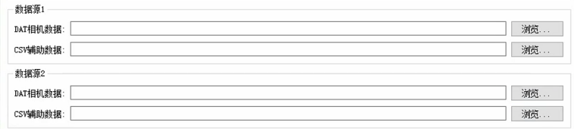
- Random Sensor Mode requires two data sources: .dat camera data and .csv auxiliary data files (select via browse).
CXP3 Normal Mode
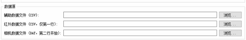
Parameter configuration is similar to Random Sensor Mode. CXP3 requires selection of auxiliary data file, infrared data file, and camera data file. Infrared data file is sent as first line, with camera data file starting from second line.
Frame Header/Trailer Settings
Used to configure frame header and trailer identifiers for data packets, including value and K-code components.
- Frame Header/Trailer Value: User-defined identification data.
- K-code Identifier: 1 for K-code, 0 for D-code.
Note: In Transparent Transmission Mode, frame headers and trailers stored in files must follow little-endian format (lower 8 bits stored at lower addresses, upper 8 bits at higher addresses). Incorrect endianness will prevent frame boundary recognition and cause acquisition failure. Example: Configured value 0x1234 should be stored as [0x34, 0x12] in memory/file.
PCIe1004 Data Acquisition System
Composition
The CoaXPress Data Acquisition System mainly consists of a CoaXPress data acquisition module, data receiving host, and CoaXPress cables. The CoaXPress data acquisition module uses Hello FPGA's PCIE-1004 4-CHANNEL COAXPRESS GRABBER board, with the main control upper computer software of the data receiving host using supporting software for the acquisition module. Configuration via the upper computer software enables storage of four-channel independent data with different line rates and structures.
The CoaXPress Data Acquisition System must work with the Camera CoaXPress Data Simulation Source described in Section 1, requiring acquisition of four-channel CoaXPress data output with different line rates and structures from the simulation source. Therefore, the four GT core configurations of the CoaXPress data acquisition module also need to be reconfigurable.
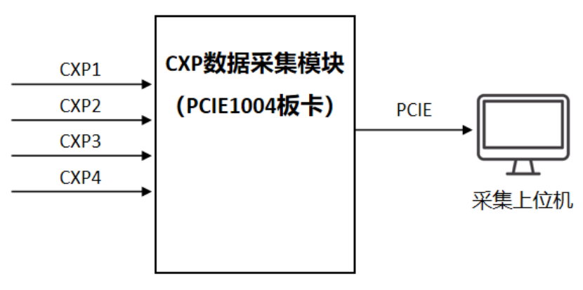 Figure -2 Camera CoaXPress Data Simulation Source Composition Diagram
Software Description
CXP 0, 1, 2, 3 represent the four hardware GT ports (0123), with independent configuration for each window. Line rates of the four GT ports are strictly configured according to protocol requirements, and the upper computer allows selecting which GT port to acquire from different windows.
Parameter Configuration:
- Target Acquisition Parameter: Configure number of frames per acquisition (-1 for continuous reading).
- Clock Cycles per Frame: Number of clock cycles per frame (including frame header and trailer length).
- Bytes per Clock Cycle: Number of bytes per clock cycle (fixed at 2 bytes per current protocol).
- Final Acquired Data Volume = Target Acquisition Parameter × Clock Cycles per Frame × Bytes per Clock Cycle
The top section of the upper computer allows browsing storage paths for saving acquired data packets and selecting formats (currently bin and dat). Saved files follow naming convention consisting of channel number and acquisition time.
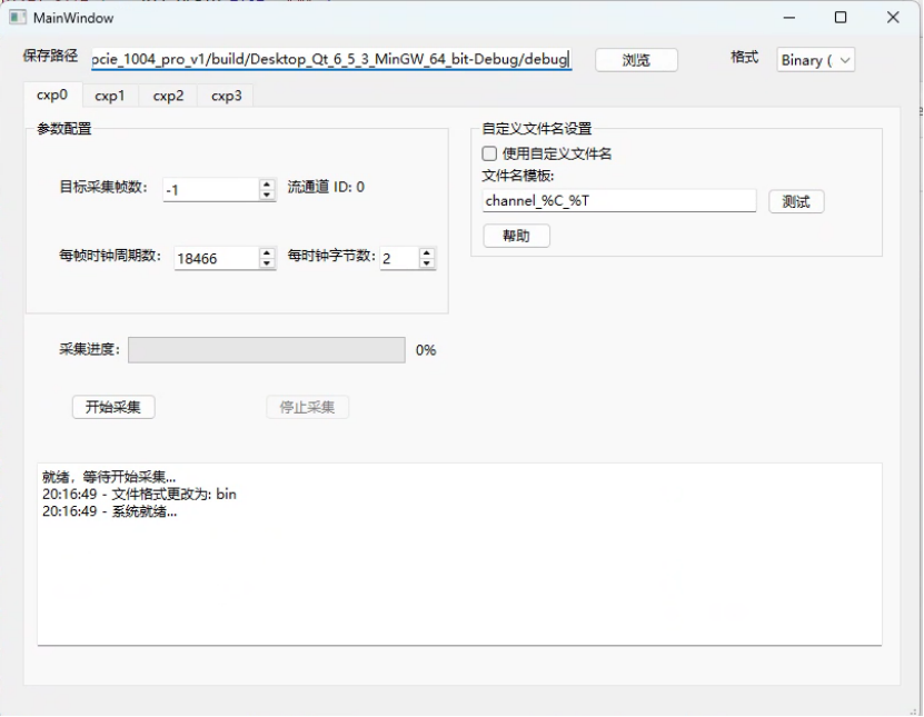 Figure -3 Acquisition System Upper Computer Software Interface
The top section of the upper computer allows browsing storage paths for saving acquired data packets and selecting formats (currently bin and dat). Default saved file format consists of channel number and acquisition time.
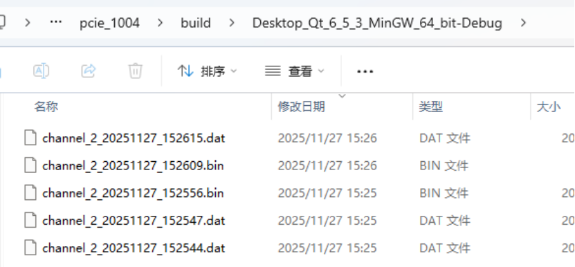 Figure -4 Saved File Format Example